Procedure:
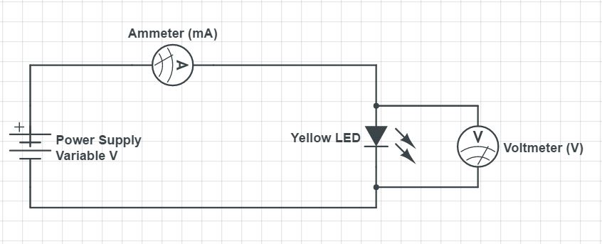
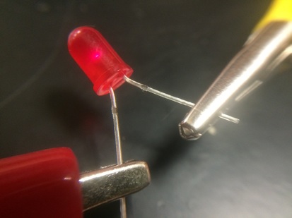
We decided to create a basic circuit (shown below) to measure both the voltage and current in order to find if LEDs actually obey Ohms Law by using the Ohms Law equation: V=IR. After making the circuit diagram, we constructed our own circuit (shown right).
|

|
In order to collect the data, we varied the voltage on the power supply and then recorded the data from the ammeter and the voltmeter. This gave us both the current through the circuit as well as the voltage across it. We conducted our experiment three times, but ran into significant issues on each trial. The extent of the issues will be presented below the table/graph, but the reasons for why will be discussed in the discussion section. From the experimentation of the yellow LED, we collected the following data:
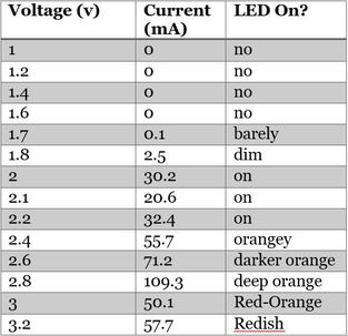
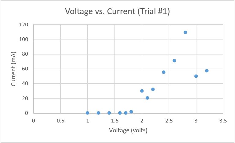
Yellow LED - Trial #1
|
|
We only started noticing any sign that the LED was on at around 1.7v. After about 2.4v however, the data just starts to get very strange; with values varying by as much as 40mA. We concluded that there may be a range of voltage in which LEDs can operate before strange things start happening.
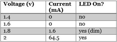
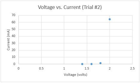
Yellow LED - Trial #2
|
|
For this trial, the LED seemed to be working fine at first, but after reaching 2 volts, the voltmeter simply stopped reading anything higher. Thus, being unable to record any higher voltage, we stopped this trial at 2 volts. This was the second most prominent problem we encountered. With none of our teachers being able to explain why this happened, we concluded that there must have been some error with our setup; such as a student from a different class altering the settings made from the previous day.
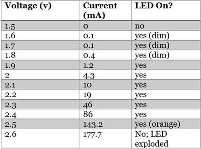
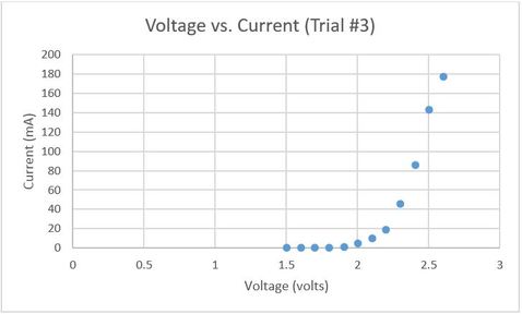
Yellow LED - Trial #3
|
|
After running into so many difficulties with the electronic multi-meters working as our ammeter and voltmeter respectively, we decided to swap out the multi-meters in exchange for analog meters instead. This provided the most accurate data ironically, but after the voltmeter reached a reading of 2.6v, the LED sparked and started smoking; thus signaling the end of the final trial. The resulting LED looked like the following:
Normal functioning LED
|
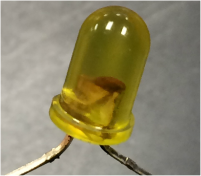
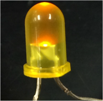
Damaged LED
|
We were unable to determine what the material covering both of the terminals in the damaged LED is.
This final trial of the Yellow LED did however give us the most definitive proof that LEDs do not obey Ohms law. The graph is clearly not linear, resembling more of an inverse curve, with the LED showing no current or any indication that it is on until about 1.5v are applied across it. The graph also shows clearly the point at which the LED becomes overpowered and dies (quite spectacularly in our case) when the voltage hit 2.6v.
This final trial of the Yellow LED did however give us the most definitive proof that LEDs do not obey Ohms law. The graph is clearly not linear, resembling more of an inverse curve, with the LED showing no current or any indication that it is on until about 1.5v are applied across it. The graph also shows clearly the point at which the LED becomes overpowered and dies (quite spectacularly in our case) when the voltage hit 2.6v.
Red LED - Trial #1
In order to see if the color of the LED plays a role in how the LED operates, we decided to also test a red LED, using the same procedure as we did for the yellow. From our previous experience, we tested the LED by varying the voltage and recording the current.
Here is the data table and graph we constructed from our trial one data:
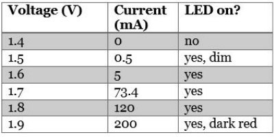
|
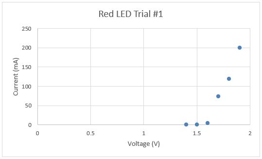
|
This data is very similar to the data collected with the yellow LED; the key difference being that the LED started to light up at 1.5v instead of 1.7v. The graph also shows the same exponential rate of change that we found with the yellow LEDs. The LED did cut out again at 2v, like it did in in trial #2 of the yellow LED. We are still unsure of the cause of this sudden freezing of voltage across the LED, but visit our discussion page for a more detailed explanation.
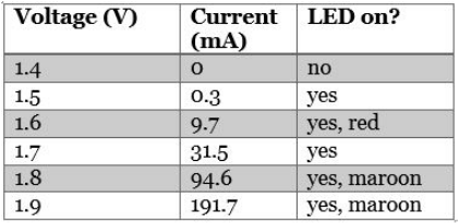
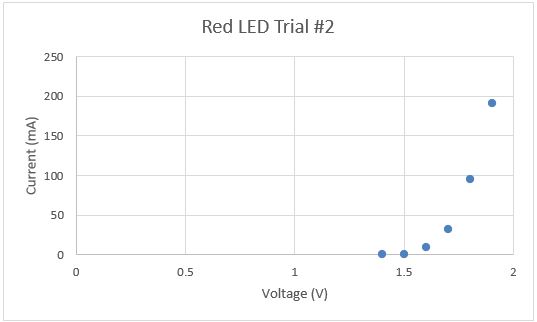
Red LED - Trial #2
|
|
Again, with a new red LED, the data showed the same exponential curve (albeit more defined) with a starting point at 1.5v and an ending voltage of 2v.
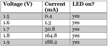
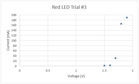
Red LED - Trial #3
|
|
This time, the red LED still showed the same start and end points, however from 1.7 to 1.8 volts there was a significant jump in current; from 30.8mA to 164.8mA. This most likely was just an inaccuracy in the data coming from a defective LED. This inaccurate data can occur very often, since the ability to test using our setup has a very small window in which to test voltage before the LED begins to malfunction.
To learn more about some of the causes and in depth look into the problems faced in this lab, click the button below to go to our discussion page.
