Discussion
Sporadic Data
In our first trial of the lab, our data was incredibly sporadic; with current values jumping around with seemingly no relationship to the amount of voltage put in. From this, we concluded that there must be a range of currents/voltages in which the LED operates, but upon further research, we discovered an explanation for our odd data. According to the LED center, because LEDs are diodes, the relationship between current and voltage is exponential, not linear; meaning that, "...a small change in voltage can produce a huge change in current..." (Arnold). The article goes on to state that there id no real way to know exactly the relationship between the current and the voltage of an LED, because each one can vary based on differences in color, size, and even different batches of LEDs. This is why, the article states that when using LEDs, it is important to add a resistor to the setup in order to limit the current going through the LED, since resistors can allow the LED to operate at a safe voltage without reaching a current spike (something that could have been the cause of numerous of what seemed to be "dud" LEDs, or LEDs that simply wouldn't turn on regardless of the voltage put across them.
Had we looked more carefully at how LEDs are rated, we would have discovered that when buying LEDs, for example, they come with a rating such as: 3.3V @ 20mA typical. That means that there is a tested voltage at which the LED is considered to operate safely, but even then, as the article described, "...being 'off by a little' in the forward voltage can have a drastic effect in the current" (Arnold).
If we had used a resistor during our experiment, we would have gotten current values that do not fully reflect the effects of even small amounts of forward voltage on an LED.
Possible Reasons for Data Inconsistencies
During the course of our experimentation, we found there to be many explained and unexplained data inconsistencies. While some of this is inherently due to the way in which we collected data, by not using a resistor to limit the current, some issues, such as voltage readings across the LED stopping at 2v, as well as massive current fluctuations may have occurred for a variety of other reasons. The first, according to Mr. Eck, a Physics teacher at Brighton High School, could be due to inconsistencies in the school power. Given that various amounts of power are being used in the school throughout the day, there is a chance that if more or less power was being used on one day than another, there could be differences in exactly how much current was flowing through the wires at any given moment.
Another possible culprit for data inconsistencies could be that given that this experiment was conducted over the course of two weeks, there is a chance that someone may have altered the settings for constant current on the power supply, switched cabling or in some other capacity altered the setup, thereby damaging the LED; resulting in inaccurate data.
Also, given that we were measuring in mA, not Amperes, there is a possibility that if the voltage knob (which measures only to a tenth of a volt) is turned a slightly different amount on one test than on another, since the voltage will look the same on the voltimeter, we will not know the difference, while the ammeter will, since it is far more sensitive.
Finally, since temperature controlled in the classroom in which we tested, it is possible that the change in temperature over days, but even minutes, could alter the amount of resistance within the wires, thus again resulting in differing data from trial to trial.
How to Improve the Experiment
To increase the validity of our experiment, we could have changed several things with how we conducted our experiment. For example, if we had more LEDs, we could have done more trials with the red and yellow LEDs to see if there were any consistencies with a larger data set. A larger sample size would have eliminated the effect of any outliers and in turn generated more accurate data.
Additionally, investigating the current and voltage of a variety of colored LEDs (besides yellow and red) could have given us a better idea of how the hue of the light emitted on the electro-magnetic radiation spectrum could have correlated to differing voltage and current data.
The reason we got faulty data was because the question we asked was inherently incorrect. LEDs cannot obey Ohm's Law, since they are not basic resistors, they are diodes (more specifically, semiconductors). They might have some resistance, but this is in no way in direct relation to the current as is the case for a resistor.
However, there is an alternate experiment we could perform that applies Ohm's law to LEDs. When most people work with a basic LED circuit, a resistor is added in series with the LED to reduce current flow so as to not damage the LED. If one puts a certain current through a battery, they can use the Ohm's Law equation to find the resistor needed to produce that current. Conversely, one can put in the value of a resistor into this equation and find the current that will be produced by it ("LED Resistor Calculator"). We found a website claiming that one could use a modified versions of the Ohm's law equation to find these values:
R = (V(s) - V(led))/ I(led)
In this situation, R is the resistance, V(s) is the voltage of the power source and V(led) is the voltage drop across the LED. I(led) is the current through the LED. The website we found stated that the typical voltage drop across a red or yellow LED was about 1.8 volts, so we used that in our calculations ("LED Resistor Calculator"). What the website seems to claim is that the current produced from the LED should follow Ohm's law depending on the voltage across the whole circuit (hence subtracting the voltage drop of the LED). If we were to write the equation in terms of current, we would find this:
I(led) = (V(s) - V(led))/R
Using this equation, we can predict the current through the LED with different resistors. We decided to keep voltage constant at 6 volts and used the same LED. All we varied was the resistor used. Using the equation, we calculated the predicted current that would go through a red LED with a source voltage of 6 volts with a resistor of 100 Ohms.
I(led) = (V(s) - V(led))/R
I(led) = (6 - 1.8)/100
I(led) = .42
I(led) = (6 - 1.8)/100
I(led) = .42
The amount of current the formula predicted was .42A or 42 mA. We repeated this process with different resistors we had on hand. Then, using our same experimental setup with a resistor in series with the LED and battery, we measured the current using the ammeter. Below is the data we produced as well as the percent error between the measured and predicted currents:
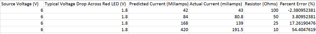
We only performed one trial given that it was a speculative experiment, but the one trial yielded surprising results. Instead of behaving like the equation predicted, as the resistance of the resistor dropped, the difference between the predicted current and the actual current increased. The percent error using the 10 Ohm resistor had a 50 percent error, which is significant. Even in this situation of varying resistors, the LED still did not obey Ohm's law.
This finding however, could be due to a multitude of factors. Firstly, the LED could have had a voltage drop across it that was something other than 1.8 Volts. Even then however, the rate of change should be linear, since the voltage drop should be constant. The easiest explanation is that again, the LED is simply not a resistor and therefore will not act like one. There is no equation that describes the relationship between
the current going through and resistance of the LED, meaning that there could be extra resistance encountered by the current as it goes through the LED. Nevertheless, it would be interesting to perform several trials to see if this phenomenon persisted in different colored and types of LEDs.
What is the Relationship Between the Voltage Range of the LED and Its Color?
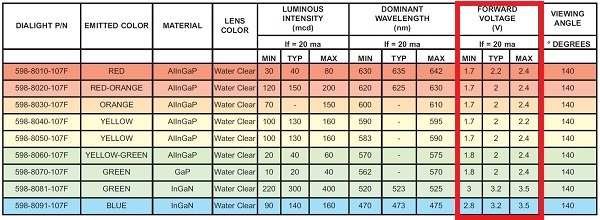
As previously stated, the LED has a band gap, or a range of energies across which the electrons in the LED cannot be. When the silicon in the LED is doped, then electrons with a potential difference of about 1 to 2 volts can cross the gap, causing energy to be released and light to be produced. The voltage of the electrons determines the wavelength of the light on the electro-magnetic spectrum, which produces different colors ("Band Theory"). This phenomenon is observed in a LED when the source voltage is above or below a certain voltage range for that color LED. The LED does not turn on. However, for each different color of a given LED, the voltage range is different ("Basic Light Emitting Diode Guide"). Below is a table of values that gives the forward voltage (or source voltage) range of a given color of LED:
http://dangerousprototypes.com/blog/wp-content/media/2012/10/LED_FWV1.jpg
The table reflects our data quite accurately. Both the red and yellow have a forward voltage minimum of about 1.7 Volts, which is when the LEDs tended to start emitting light. Additionally, the LEDs tended to illuminate the brightest at 2 volts, and many burnt out at about 2.4 volts. This was incredibly interesting, since the effect of the band gap on the LED is illustrated both from the table and in the actual experimentation we conducted.
For information about any of the sources used on this website, please click on the button below to be taken to the works cited page.
For information about any of the sources used on this website, please click on the button below to be taken to the works cited page.
